

Products Description
Solid Oxide Fuel Cells (SOFCs) represent a transformative technology in electrochemical energy conversion. Unlike conventional combustion-based power generation, SOFCs directly convert chemical energy from fuels like hydrogen or methane into electricity with high efficiency (60–85%) and minimal emissions. Their core architecture relies on ceramic-based ionic conductors, enabling operation at elevated temperatures (500–1000°C). This article explores the structural diversity of SOFCs, their material science foundations, manufacturing techniques, and evolving applications across industries.
Tubular vs. Planar SOFCs: Design and Trade-offs
1. Tubular SOFCs
Pioneered by Siemens Westinghouse Power Corporation (SWPC), tubular SOFCs are cylindrical cells with sequential layers:

Cathode Support Tube: Porous lanthanum strontium manganite (LSM) or similar perovskite materials, formed via extrusion.
Electrolyte: Yttria-stabilized zirconia (YSZ), deposited via electrochemical vapor deposition (EVD) to ensure gas-tightness.
Interconnect: Doped lanthanum chromite (LaCrO₃) or metallic alloys (e.g., Crofer 22 APU), applied via plasma spraying.
Anode: Nickel-YSZ cermet, screen-printed or slurry-coated.
Advantages:
Robust Mechanical Integrity: Cylindrical geometry minimizes thermal stress, enabling rapid thermal cycling.
No High-Temperature Seals: Fuel and air channels are inherently separated, simplifying stack assembly.
Limitations:
Low Power Density (~0.2 W/cm²): Long current paths increase ohmic losses.
High Fabrication Costs: EVD and plasma spraying are energy-intensive and require specialized equipment.
Innovations:
SWPC's Flat-Tube Design: Combines tubular resilience with planar-like current paths, boosting power density to ~0.35 W/cm².
Microtubular SOFCs: Sub-millimeter tubes (e.g., Acumentrics' designs) achieve rapid startup (<10 minutes) and 1–5 kW outputs for portable power.
2. Planar SOFCs
Planar cells adopt a flat, layered "Positive-Electrolyte-Negative" (PEN) structure, offering:
High Power Density (0.5–1.0 W/cm²): Short, vertical current paths reduce resistance.
Scalable Manufacturing: Tape casting, screen printing, and co-sintering enable mass production.
Challenges:
Thermal Stress Management: Mismatched thermal expansion coefficients (TECs) between layers can cause delamination.
Sealing Complexity: Glass-ceramic seals must withstand thermal cycling while isolating fuel/air streams.
Material Innovations:
Electrolytes: Scandia-stabilized zirconia (ScSZ) for enhanced ionic conductivity at 750°C.
Interconnects: Ferritic stainless steels (e.g., Crofer 22 APU) with protective coatings (e.g., MnCo₂O₄) to resist oxidation.
Structural Support Types: From Electrolyte to Metal
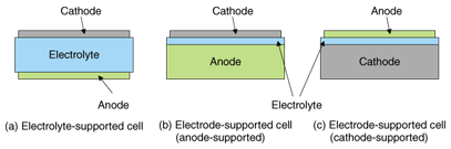
1. Electrolyte-Supported Cells
As the first-generation SOFCs, these cells use thick YSZ electrolytes (100–200 μm) for mechanical stability but require high temperatures (900–1000°C) to overcome low ionic conductivity.
Sulzer Hexis' Design: Combines electrolyte support with radial gas flow, achieving 40% electrical efficiency in residential CHP systems.
Bloom Energy's ES-5700: A commercial 200 kW stack operating at 950°C, leveraging low-cost calcia-stabilized zirconia.
Limitations:
High Degradation Rates: Electrolyte cracking due to redox cycling.
Slow Startup: Unsuitable for mobile applications.
2. Anode-Supported Cells
By shifting the support role to a thick Ni-YSZ anode (~1 mm), operating temperatures drop to 700–800°C.
Julich's Stack: Achieves 0.6 W/cm² at 750°C using vacuum slurry coating for thin YSZ electrolytes (5–10 μm).
Degradation Mechanisms: Nickel coarsening and sulfur poisoning reduce long-term stability.
Market Adoption:
Tokyo Gas' ENE-FARM: A 700 W residential system with 90% fuel utilization.
GE's Hybrid Systems: Integrating SOFCs with gas turbines for >65% efficiency.
3. Cathode-Supported Cells
These cells prioritize cathode mechanical support, ideal for tubular designs.
SWPC's Segmented-in-Series Design: Stacking corrugated cathode tubes achieves 50 kW outputs.
Material Challenges: Sr-doped LaMnO₃ (LSM) cathodes react with YSZ above 1200°C, necessitating gadolinium-doped ceria (GDC) interlayers.
4. Metal-Supported Cells (MSCs)
Stainless steel substrates enable rapid thermal cycling (500–600°C) and compatibility with automotive applications.
DLR's Innovations:
Diffusion Barriers: La0.6Sr0.2Ca0.2CrO3+δLa0.6Sr0.2Ca0.2CrO3+δ layers prevent Fe/Cr migration into the anode.
Atmospheric Plasma Spraying (APS): Deposits dense electrolytes in open-air conditions, cutting costs by 30%.
Ceres Power's SteelCell™: A 5 kW stack using ferritic steel and CGO electrolytes, targeting £1,000/kW production costs.
Applications:
Automotive APUs: Nissan's SOFC-powered e-NV200 van extends EV range by 500 km.
Aerospace: DLR's 3 kW APU for aircraft auxiliary power.
Manufacturing Techniques: Bridging Lab and Industry

1.Electrochemical Vapor Deposition (EVD):
Process: Reacting metal chlorides (e.g., ZrCl₄) with steam to form dense YSZ films.
Use Case: SWPC's tubular cells.
2.Tape Casting and Co-Sintering:
Steps: Casting anode/electrolyte/cathode layers as green tapes, laminating, and firing.
Advantage: High-throughput production of planar cells.

3.Plasma Spraying:
Types: Vacuum (VPS) for dense coatings; atmospheric (APS) for cost-sensitive applications.
4.Wet-Chemical Methods:
Dip Coating: Shanghai Institute of Ceramics' LSM cathodes.
Electrophoretic Deposition (EPD): Ceres Power's CGO electrolytes.
Performance Metrics and Challenges
Power Density: Ranges from 0.2 W/cm² (tubular) to 1.2 W/cm² (advanced planar).
Degradation Rates: <1%/1,000 hours for metal-supported cells vs. 2–5%/1,000 hours for anode-supported designs.
Lifetime Targets: 40,000 hours for stationary systems; 10,000 cycles for automotive APUs.
Key Challenges:
1.Material Compatibility: Mitigating interfacial reactions (e.g., Ni-YSZ/steel interdiffusion).
2.Cost Reduction: Scaling production of rare-earth materials (e.g., scandia, gadolinium).
3.System Integration: Balancing fuel reformers, heat exchangers, and power electronics.
Future Directions and Emerging Technologies
1.Low-Temperature SOFCs (LT-SOFCs):
Goal: Operate below 600°C using proton-conducting electrolytes (e.g., BaZr₀.₈Y₀.₂O₃).
Benefits: Compatibility with stainless steel components and faster startup.
2.3D-Printed SOFCs:
Advantage: Customizable geometries for optimized gas flow and current collection.
Example: ORNL's additive-manufactured PEN structures.
3.Nanostructured Materials:
Nanofiber Electrodes: Higher surface area for enhanced catalytic activity.
Atomic Layer Deposition (ALD): Ultra-thin, defect-free electrolyte films.
4.Hybrid Systems:
SOFC-Gas Turbine: Achieving >70% efficiency in megawatt-scale plants.
SOFC-Battery: Hybridizing with Li-ion for grid stability.
Conclusion
SOFC technology stands at the crossroads of material innovation and industrial scalability. While tubular designs excel in durability and planar cells dominate high-power applications, metal-supported variants are unlocking new frontiers in mobility and decentralization. Advances in manufacturing-from plasma spraying to 3D printing-are driving down costs, while nanomaterials and hybrid systems promise unprecedented efficiency. As global energy systems transition toward decarbonization, SOFCs are poised to play a pivotal role in bridging the gap between renewable intermittency and reliable power delivery.
References:
Kendall, K. Microtubular SOFCs: From Concept to Commercialization. Elsevier, 2015.
Wachsman, E. D. Solid Oxide Fuel Cells: Materials Properties and Performance. CRC Press, 2016.
Blum, L. Metal-Supported SOFCs: Advances and Challenges. Journal of Power Sources, 2021.
Industry reports from Bloom Energy, Ceres Power, and Siemens Energy.